


The Anatomy of an Electric Hydraulic Pump: A Comprehensive Guide to Its System Components
An electric hydraulic pump is far more than just a motor and a pumping mechanism. It is a meticulously engineered, integrated system designed to convert electrical energy into controlled, powerful hydraulic energy. Whether it is a compact power unit for a workshop press or a large industrial station for a manufacturing plant, understanding the individual components that make up this system is crucial for proper selection, maintenance, and troubleshooting.
Each component plays a specific and vital role. The motor provides the muscle, the pump creates the flow, the valves direct and control the energy, and the reservoir manages the lifeblood of the system—the hydraulic fluid. This guide will dissect an electric hydraulic pump system, exploring the function, types, and importance of each core component, providing a complete anatomical overview of this indispensable piece of equipment.
Chapter 1: The Prime Mover – The Electric Motor
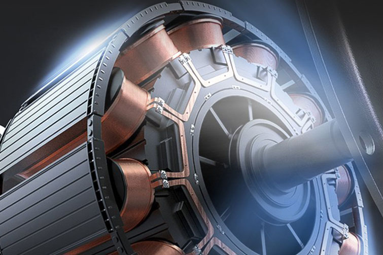
At the heart of every electric hydraulic pump is the electric motor. Its job is to convert electrical energy into mechanical rotational force (torque) to drive the hydraulic pump. The selection of the motor has a direct impact on the pump's performance, efficiency, and suitability for a given application.
1.1 Power Source: AC vs. DC
- AC Motors (Alternating Current): These are the standard for most industrial and stationary workshop applications. They are available in single-phase (common in residential and light commercial settings, e.g., 115V or 230V) and three-phase (standard in industrial environments, e.g., 230V, 460V, or 575V). Three-phase motors are generally more efficient, provide a smoother start, and have a longer life than their single-phase counterparts for a given horsepower.
- DC Motors (Direct Current): These are used in mobile applications where AC power is not available, such as in vehicles, aircraft, or battery-powered equipment. They typically run on 12V, 24V, or 48V systems from a battery. They are designed for intermittent duty cycles to preserve battery life.
1.2 Horsepower and Torque
The motor's power rating, expressed in horsepower (HP) or kilowatts (kW), determines the total amount of work the pump unit can perform. It must be sufficient to meet the combined demands of pressure and flow from the hydraulic system. An undersized motor will struggle, overheat, and may trip its overload protection. The relationship is defined by the hydraulic horsepower formula: HP = (Flow in GPM × Pressure in PSI) / 1714. This calculation dictates the required motor size.
1.3 Enclosure Types
The motor's housing protects its internal components from the environment.
- Open Drip Proof (ODP): Suitable for clean, dry, indoor environments where no liquids or airborne contaminants are present.
- Totally Enclosed Fan Cooled (TEFC):) The most common type for industrial use. A fan on the motor shaft blows air over the enclosed housing to cool it. It prevents the exchange of outside air with the motor's interior, protecting against dust, dirt, and moisture.
- Explosion-Proof: A specialized, heavily constructed enclosure designed to contain any internal spark or explosion, preventing it from igniting flammable gases or vapors in the surrounding atmosphere. These are mandatory in hazardous locations.
Chapter 2: The Heart of the System – The Hydraulic Pump
This is the component that does the primary work of the power unit. Driven by the electric motor, it creates flow by displacing fluid from the reservoir and pushing it into the hydraulic system.
2.1 Basic Principle of Operation
All non-dynamic hydraulic pumps are "positive displacement" pumps. This means that for each revolution of the pump's input shaft, a fixed (or nearly fixed) volume of fluid is trapped, moved, and discharged into the system. This is what allows a hydraulic system to generate very high pressures—the pump continuously pushes fluid until the resistance to flow (the load) creates pressure.
2.2 Common Pump Types
- Gear Pumps (External): The most common and robust type. Two meshing gears rotate inside a close-fitting housing. Fluid is carried around the outside of the gears from the inlet to the outlet. They are inexpensive, tolerant of some contamination, and ideal for pressures up to 3,000 PSI. They are a staple in log splitters, lifts, and many industrial power units.
- Vane Pumps: A slotted rotor with sliding vanes spins inside a cam ring. Centrifugal force and pressure push the vanes outward against the ring, creating chambers that expand and contract to draw fluid in and push it out. They are quieter than gear pumps and have lower flow ripple, making them suitable for industrial machinery where noise is a concern.
- Piston Pumps (Axial): The most efficient and high-performance type. An array of pistons within a rotating cylinder block reciprocates as they ride on a swashplate. This action draws fluid in and pushes it out. They can operate at very high pressures (over 10,000 PSI) and can be designed for variable displacement, allowing the pump's output flow to be changed on demand. They are used in heavy-duty applications like excavators and large presses but are expensive and sensitive to contamination.
2.3 Two-Stage (Log Splitter) Pumps
A clever variation often found in mobile and workshop equipment is the two-stage pump. It contains two pumping sections—one high-flow, low-pressure, and one low-flow, high-pressure. It automatically switches between them, providing fast approach speed under light load and immense power under heavy load, all without requiring an oversized motor.
Chapter 3: The Fluid Manager – The Reservoir (Tank)
The reservoir is far more than just a storage tank for hydraulic fluid. It performs several critical functions that directly affect the health and performance of the entire system.
- Fluid Storage: Its primary and most obvious role is to hold the volume of hydraulic fluid required by the system when the cylinders are retracted.
- Heat Dissipation: As hydraulic fluid works, it generates heat. The reservoir's surface area allows this heat to dissipate into the surrounding air. A larger reservoir provides better cooling, which is vital for systems with high-duty cycles.
- Contaminant Settlement: The reservoir provides a place for fluid to rest, allowing heavier contaminants like metal wear particles to settle to the bottom, where they can be trapped by a magnet or drained away.
- Air Separation: When fluid returns to the tank, it often carries entrained air bubbles. The larger surface area and relatively still fluid in the reservoir allow these bubbles to rise to the surface and escape, preventing aeration (spongy and inefficient system operation).
- Key Features: A well-designed reservoir includes a filler-breather cap (to allow air to enter/exit as fluid level changes while filtering incoming air), a sight glass or dipstick (to check fluid level), and a drain plug at the lowest point for fluid changes.
Chapter 4: The Brains and Muscles – Hydraulic Valves
Valves are the control elements of the system, directing and regulating the flow and pressure of the hydraulic fluid.
4.1 Pressure Control Valves
- Pressure Relief Valve: The single most important safety component in any hydraulic system. It is a normally closed valve set to open at a predetermined maximum pressure (the system's pressure setting). If the pressure exceeds this limit (e.g., a cylinder reaches the end of its stroke), the relief valve opens, diverting pump flow back to the reservoir. This prevents the pump from building destructive pressure that could burst hoses or damage components.
- Pressure Reducing Valve: Used to create a lower, consistent pressure in a branch of the hydraulic circuit. For example, a high-pressure main circuit might power a press, while a pressure-reducing valve supplies a lower, safe pressure for a clamping circuit.
4.2 Directional Control Valves
These valves determine the path that the hydraulic fluid takes, thereby controlling the direction of movement of the actuators (cylinders or motors).
- Spool Valves: The most common type. A precision-machined spool slides within a bore, connecting different ports (P for pump, T for tank, A and B for actuator) depending on its position.
- Manual vs. Solenoid Operated:Manual Valves: Operated by a lever or handle. They are simple, reliable, and provide direct tactile control. Common on basic equipment like log splitters.Solenoid Valves: Operated by electrical coils. When energized, the solenoid pulls the spool into position. This allows for remote control, automation, and integration with programmable logic controllers (PLCs) in industrial machinery.
- Center Configurations: The "normal" position of a 4-way, 3-position valve (often called "tandem center," "closed center," etc.) dictates what happens to the pump flow and actuator when the valve is in neutral. This is a critical design consideration.
4.3 Flow Control Valves
These valves regulate the speed of an actuator by controlling the rate of fluid flow. A simple needle valve, often combined with a check valve to allow free flow in one direction and controlled flow in the other, is a common way to control cylinder speed.
Chapter 5: The Plumbing and Protection
The major components would be useless without the means to connect them and protect the fluid's integrity.
5.1 Hydraulic Fluid
The lifeblood of the system. It transmits power, lubricates moving parts, seals clearances, and cools the system. The correct fluid viscosity (weight) and type (e.g., standard mineral oil, fire-resistant, biodegradable) must be used as specified by the manufacturer.
5.2 Filters and Strainers
Contamination is the leading cause of hydraulic component failure.
- Suction Strainer: A coarse mesh screen located inside the reservoir on the pump's inlet line. It protects the pump from large particles.
- Return Line Filter: A more sophisticated filter located in the line returning fluid to the tank. It captures smaller wear particles generated by the system, ensuring only clean fluid re-enters the reservoir.
- Breather Filter: The "breather" part of the filler cap filters the air that is drawn into the reservoir as the fluid level changes, preventing airborne dust from contaminating the fluid.
5.3 Hydraulic Hoses, Tubes, and Fittings
These are the arteries and veins of the system, carrying fluid between components.
- Hoses: Flexible, used to connect parts that move or vibrate. They consist of an inner tube, reinforcement layers (wire braid or spiral), and an outer cover.
- Tubes (Pipes): Rigid, used for permanent connections between stationary components.
- Fittings: The connectors that join hoses and tubes to components. They must be compatible with the thread types (e.g., NPT, SAE, BSP) and pressure ratings of the system.
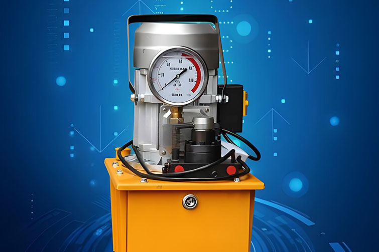
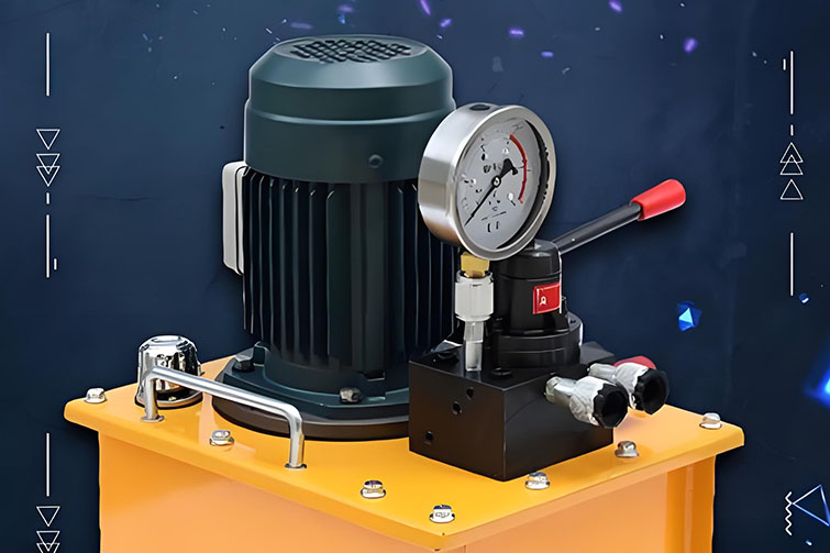
5.4 Pressure Gauge
Often an overlooked but vital component. A pressure gauge, usually installed near the pump outlet, provides a visual indication of system pressure. This is essential for:
- Setting the System: Adjusting the pressure relief valve to the correct setting.
- Monitoring Operation: Observing pressure spikes or drops can help diagnose problems like a sticking valve, a leaking cylinder, or an overloaded condition.
Chapter 6: Integration – The Power Unit
In practice, these components are often combined into a single, integrated package known as a hydraulic power unit (HPU) . In a typical HPU:
- The electric motor is mounted vertically or horizontally on top of the reservoir.
- The hydraulic pump is coupled directly to the motor shaft and is often submerged in the fluid (for vertical units) to ensure prime and reduce noise.
- The directional control valve is often mounted directly to a manifold block on top of the pump or reservoir, simplifying plumbing and reducing leak points.
- A pressure relief valve is built into this manifold or the pump itself.
- A return line filter is mounted on the reservoir.
This integration creates a compact, efficient, and relatively clean package that can be easily installed and connected to the external actuators.
Conclusion
An electric hydraulic pump is a symphony of mechanical and hydraulic engineering. From the powerful hum of the electric motor to the precise movement of a control valve spool, every component has a distinct and critical purpose. The motor supplies the energy, the pump converts it into fluid flow, the valves direct it, the reservoir manages and cools it, and the filters protect it. Understanding the function and interaction of these components is the foundation for making informed purchasing decisions, performing effective maintenance, and accurately diagnosing problems, ensuring that this powerful tool remains a reliable asset for years to come.